
Explore the foundational seven additive manufacturing process families as defined by ASTM F42. This guide offers a concise yet insightful snapshot of each pillar, designed to provide clarity and understanding without overwhelming detail. Whether you’re new to additive manufacturing or deepening your expertise, this overview highlights the core methods shaping the future of industrial production.
Laser Powder Bed Fusion
Metallic Alloys
Overview
Laser Powder Bed Fusion is a precision additive manufacturing process that builds metal parts layer by layer by selectively melting fine metal powder using a high-powered laser. It’s widely used in aerospace, medical, and energy sectors for producing complex, high-performance components.
Process Steps
Post-Processing
Excess powder is removed, and parts may undergo heat treatment, support removal, surface finishing, or HIP (Hot Isostatic Pressing) to enhance mechanical properties.
Powder Spreading
A thin layer (~20–100 µm) of metal powder is evenly distributed across the build platform using a recoater blade or roller.
Laser Melting
A high-intensity laser scans the powder bed, melting and fusing particles according to a 3D CAD model. The laser path is tightly controlled for accuracy.
Layer-by-Layer Build
The build platform lowers incrementally, and new powder layers are added and fused. This cycle repeats until the full part is formed.
Build Volumes
- Most common Laser Powder Bed Fusion (LPBF) printer build sizes, along with estimated usage percentages based on industry adoption trends and manufacturer data:
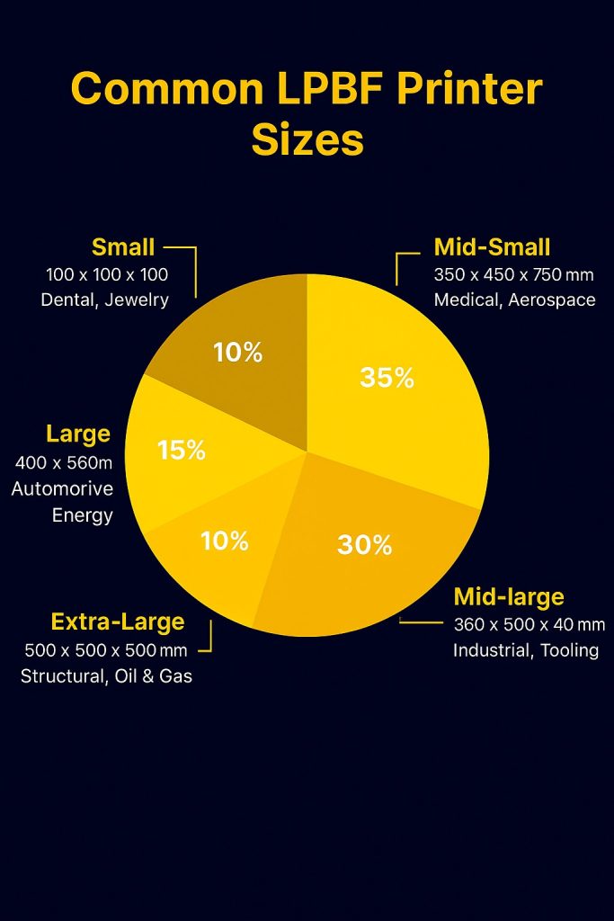
- 🧠 Notes on Usage Trends
- 📈 Mid-range formats (250–400 mm) dominate due to their balance of throughput, resolution, and versatility across industries.
- 🏥 Medical and aerospace sectors favor mid-small formats for precision and material control.
- 🏗️ Oil & gas and energy applications increasingly adopt large-format machines for structural components and API 20S-qualified parts.
- 🧪 Small-format systems remain popular for R&D, prototyping, and high-resolution niche parts.
- These percentages are approximations based on manufacturer data and industry surveys, including insights from EBM Machine and All3DP.
Typical Materials
- Titanium alloys (e.g., Ti-6Al-4V)
- Stainless steels (e.g., 316L)
- Nickel-based superalloys (e.g., Inconel 718)
- Aluminum alloys (e.g., AlSi10Mg)
- Cobalt-chrome, Maraging steel, Tool steels
- Copper alloys
Advantages
- Exceptional geometric complexity
- High material utilization
- Strong mechanical properties
- Ideal for lightweight, custom, or internal lattice structures
Challenges
- Residual stresses and distortion
- Powder handling and reuse protocols
- Qualification and certification for critical applications
Relevant Standards
- AWS D20.1:2023 – Specification for metallic AM
- ISO/ASTM 52942:2020 – Operator qualification
- ISO/ASTM 52941:2020 – Machine acceptance
- API 20S – Qualification for oil & gas components
- DNV-ST-B203 – Metallic AM parts (includes LPBF)
Polymers
Overview
Polymer Laser Powder Bed Fusion is an additive manufacturing process that builds polymer parts layer by layer by selectively sintering thermoplastic powder using a laser. It’s widely used in aerospace, automotive, consumer goods, and medical prototyping due to its ability to produce lightweight, complex geometries without support structures.
Process Steps
- Powder Spreading
A thin layer (~100–150 µm) of polymer powder is evenly distributed across the build platform using a recoater blade or roller. - Laser Sintering
A CO₂ or diode laser selectively sinters the powder based on a 3D CAD model. The surrounding unsintered powder supports the part during printing. - Layer-by-Layer Build
The build platform lowers incrementally, and new powder layers are added and sintered. This continues until the full part is formed. - Post-Processing
Excess powder is removed (often via air blasting), and parts may undergo dyeing, surface smoothing, or infiltration depending on application needs.
Typical Materials
- Nylon 12 (PA12) – most common
- Nylon 11 (PA11) – bio-based, flexible
- TPU – flexible elastomer
- PEEK – high-performance thermoplastic
- PP – lightweight, chemically resistant
- Composite blends (glass or carbon-filled)
Advantages
- No need for support structures
- Excellent design freedom and nesting efficiency
- Good mechanical properties and surface finish
- Ideal for batch production and functional prototyping
Challenges
- Limited material diversity compared to metals
- Powder aging and reuse management
- Warping and shrinkage in large parts
- Surface porosity in unsmoothed parts
Relevant Standards
- AMSC Roadmap – Polymer AM standardization gaps
- ISO/ASTM 52900 – Terminology and process classification
- ISO/ASTM 52910 – Design guidelines for AM
- ASTM F3091 – Guide for polymer powder bed fusion
- API 20T – Additively Manufactured Polymer-Based Components for Use in the Petroleum and Natural Gas Industries
Directed Energy Deposition
Overview
Directed Energy Deposition is an additive manufacturing process that builds or repairs parts by melting material as it is deposited. It uses focused thermal energy—typically from a laser, electron beam, or plasma arc—to fuse metal wire or powder onto a substrate. DED excels in large-format builds, part repair, and hybrid manufacturing.
Core Printer Types by Energy Source
|
Printer Type |
Energy Source |
Feedstocks |
Typical Materials |
|---|---|---|---|
|
Laser-Based DED |
High-power laser |
Powder or wire |
Titanium, stainless, steel, Inconels |
|
Electron Beam DED |
Electon Beam |
Wire |
Titanium alloys, high-temp alloys |
|
Plasma/Electric Arc DED |
Plasma or arc |
Wire |
Steels, nickel alloys, titanium |
Printer Architecture Variants
- 🦾 Gantry-Based Systems
- Cartesian motion control
- Ideal for large, boxy parts
- Common in industrial repair setups
- 🤖 Robotic Arm Systems
- Multi-axis flexibility (5–7 DOF)
- Suitable for complex geometries and cladding
- Used in aerospace and energy sectors
- 🧠 Hybrid CNC + DED Machines
- Combine additive and subtractive processes
- Enable near-net-shape builds with integrated finishing
- Examples: DMG MORI LASERTEC, BeAM Magic 800
Advantages
- Large build volumes (up to several meters)
- Excellent for part repair and surface cladding
- Compatible with reactive and structural alloys
- High deposition rates (up to 10 kg/hr in some systems)
Challenges
- Lower resolution than LPBF
- Requires precise thermal control to avoid distortion
- Surface finish often needs post-machining
- Limited adoption in consumer-scale applications
Relevant Standards
- AMSC Roadmap – DED harmonization and gaps
- AWS D20.1:2023 – Specification for metallic AM
- DNV-ST-B203 – Qualification for DED parts
- API 20S – Applicable for wire-fed DED in oil & gas
- ISO/ASTM 52900 – Process classification
Binder Jetting
Overview
Binder Jetting is an additive manufacturing process that builds parts by selectively depositing a liquid binder onto a bed of powder, layer by layer. Unlike fusion-based methods, it does not use heat during printing, making it faster and more scalable for batch production. Binder Jetting is increasingly used in automotive, tooling, consumer goods, and metal component production — including applications qualifying under API 20S for oil & gas.
Process Steps
- Powder Spreading
A thin layer (~50–200 µm) of powder (metal, sand, or ceramic) is evenly distributed across the build platform using a recoater blade. - Binder Deposition
Inkjet-style printheads selectively deposit binder droplets onto the powder bed, adhering particles in the desired geometry. - Layer-by-Layer Build
The build platform lowers incrementally, and new powder layers are added and bound. The surrounding powder supports the part during printing. - Post-Processing
Parts are removed from the powder bed and typically undergo curing, depowdering, and sintering. Optional infiltration (e.g., bronze into steel) or machining may follow.
Typical Materials
- Stainless steel (e.g., 316L, 17-4PH)
- Tool steels
- Inconel and other superalloys
- Copper and bronze
- Ceramics (e.g., alumina, zirconia)
- Sand (for casting molds and cores)
Advantages
- High-speed printing and scalability
- No need for support structures
- Excellent for batch production and tooling
- Compatible with metals, ceramics, and sand
Challenges
- Requires extensive post-processing (sintering, infiltration)
- Shrinkage and distortion during sintering
- Lower mechanical properties than fusion-based AM
- Limited material diversity compared to LPBF or DED
Relevant Standards
- ISO/ASTM 52900 – Terminology and classification
- ISO/ASTM 52910 – Design guidelines for AM
- ASTM F3147 – Guide for binder jetting of metals
- API 20S – Qualification framework for AM parts in oil & gas (Binder Jetting included for certain geometries and material classes)
- AMSC Roadmap – Binder Jetting standardization gaps
Material Jetting
Overview
Material Jetting is an additive manufacturing process that builds parts by depositing droplets of photopolymer or wax-like material onto a build surface, layer by layer. Each layer is cured immediately using UV light or thermal energy. Known for its high resolution and multi-material capabilities, Material Jetting is widely used in prototyping, dental modeling, and visual mockups.
Process Steps
- Droplet Deposition
Inkjet-style printheads deposit microscopic droplets of build material onto the platform in precise patterns. - Layer Curing
Each layer is cured instantly using UV light (for photopolymers) or heat (for waxes), solidifying the geometry. - Support Material Application
A secondary printhead deposits removable support material to stabilize overhangs and complex features. - Post-Processing
Supports are removed via water jet, heat, or chemical bath. Parts may be cleaned, dyed, or coated depending on application.
Typical Materials
- Photopolymers (rigid, flexible, transparent, biocompatible)
- Waxes (for investment casting)
- Elastomers (limited flexibility)
- Multi-color and multi-property blends
Advantages
- Ultra-high resolution and surface finish
- Full-color and multi-material printing
- Ideal for visual prototypes and anatomical models
- No thermal distortion or warping
Challenges
- Limited mechanical strength and durability
- Not suitable for functional or load-bearing parts
- Material degradation over time (UV sensitivity)
- Higher cost per part compared to other AM processes
Relevant Standards
- AMSC Roadmap – Material Jetting standardization gaps
- ISO/ASTM 52900 – Terminology and classification
- ISO/ASTM 52910 – Design guidelines for AM
Material Extrusion
Overview
Material Extrusion is an additive manufacturing process that builds parts by extruding thermoplastic or composite material through a heated nozzle, layer by layer. It’s the most widely adopted AM process globally, known for its simplicity, affordability, and versatility. Often referred to as Fused Filament Fabrication (FFF) or Fused Deposition Modeling (FDM), it’s used in prototyping, tooling, and increasingly in industrial applications — including those qualifying under API 20T for thermoplastic components in oil & gas.
Process Steps
- Filament Feeding
A spool of solid filament is fed into a heated nozzle via motorized gears. - Material Extrusion
The filament is melted and extruded through the nozzle onto the build platform, following a toolpath derived from a 3D CAD model. - Layer-by-Layer Build
The build platform lowers incrementally, and new layers are deposited and fused. Cooling fans may assist solidification. - Post-Processing
Supports are removed manually or via solvent bath. Parts may be sanded, annealed, or coated depending on application.
Typical Materials
- PLA – easy to print, biodegradable
- ABS – durable, impact-resistant
- PETG – strong, chemical-resistant
- Nylon – flexible, wear-resistant
- TPU – elastomeric
- Carbon-fiber or glass-filled composites
- High-performance polymers (PEEK, ULTEM, PPS)
Advantages
- Low-cost hardware and materials
- Wide material availability
- Ideal for rapid prototyping and functional testing
- Scalable from desktop to industrial platforms
Challenges
- Lower resolution and surface finish than other AM processes
- Warping and layer adhesion issues with some materials
- Support removal can be labor-intensive
- Limited suitability for high-precision or load-bearing parts
Relevant Standards
- ISO/ASTM 52900 – Terminology and classification
- ISO/ASTM 52910 – Design guidelines for AM
- API 20T – Qualification framework for thermoplastic AM components in oil & gas
- AMSC Roadmap – Material Extrusion standardization gaps
Sheet Lamination
Overview
Sheet Lamination is an additive manufacturing process that builds parts by stacking and bonding sheets of material, layer by layer. Each sheet is cut to shape and then bonded to the previous layer using adhesive, ultrasonic welding, or thermal fusion. Known for its speed and affordability, Sheet Lamination is used in visual prototyping, packaging, and tooling — with emerging applications in metal part production and hybrid manufacturing.
Process Steps
- Sheet Placement
A sheet of material (paper, polymer, or metal foil) is placed on the build platform. - Cutting
A laser, blade, or CNC cutter slices the sheet into the desired cross-sectional geometry. - Bonding
The cut sheet is bonded to the previous layer using adhesive, ultrasonic welding, or heat. - Layer-by-Layer Build
The process repeats until the full part is formed. Excess material may be trimmed during or after the build. - Post-Processing
Parts may be machined, infiltrated (for metal), or coated. Supports are typically unnecessary due to the sheet-based structure.
Typical Materials
- Paper (for low-cost visual models)
- Polymer films (e.g., PVC, ABS)
- Metal foils (e.g., aluminum, titanium)
- Composite laminates
Advantages
- Fast and cost-effective for large parts
- Excellent for visual and conceptual models
- Minimal waste and high material utilization
- Can produce full-color prototypes (via paper lamination)
Challenges
- Limited mechanical strength and resolution
- Bonding quality affects part integrity
- Restricted to planar geometries and simple contours
- Metal sheet lamination requires extensive post-processing
Relevant Standards
- API 20T – Applicable for thermoplastic sheet lamination in oil & gas (limited use cases)
- ISO/ASTM 52900 – Terminology and classification
- ISO/ASTM 52910 – Design guidelines for AM
- AMSC Roadmap – Sheet Lamination standardization gaps
Vat Photopolymerization
Overview
Vat Photopolymerization is an additive manufacturing process that builds parts by selectively curing liquid photopolymer resin using a light source. The process is known for its ultra-high resolution, smooth surface finish, and ability to produce intricate geometries. It’s widely used in dental, jewelry, medical modeling, and microfluidics — with emerging interest in industrial-grade resins for tooling and biocompatible components.
Process Steps
- Resin Preparation
A vat is filled with liquid photopolymer resin, typically UV-sensitive. - Selective Curing
A light source (laser, projector, or LCD panel) cures specific regions of the resin layer-by-layer based on a 3D model. - Layer-by-Layer Build
The build platform moves vertically, allowing new layers to be cured atop the previous ones. The process continues until the part is complete. - Post-Processing
Parts are removed from the vat, cleaned (usually in isopropyl alcohol), and post-cured under UV light to achieve full mechanical properties. Supports are removed manually.
Typical Materials
- Standard photopolymers (rigid, flexible, transparent)
- Engineering resins (high-temp, impact-resistant)
- Dental and biocompatible resins
- Castable resins (for investment casting)
- Ceramic-filled photopolymers (experimental)
Advantages
- Exceptional resolution and surface detail
- Ideal for small, intricate, and aesthetic parts
- Broad range of specialty resins
- Minimal thermal distortion
Challenges
- Limited mechanical strength and durability
- UV sensitivity and long-term degradation
- Resin handling requires safety precautions
- Not ideal for large-scale or load-bearing parts
Relevant Standards
- API 20T – Applicable for thermoset photopolymer components in oil & gas (limited use cases, typically non-load-bearing)
- ISO/ASTM 52900 – Terminology and classification
- ISO/ASTM 52910 – Design guidelines for AM
- AMSC Roadmap – Vat Photopolymerization standardization gaps